2015-10 IPFire 2.13 Core 75
Installation
We will build a complete IPFire (2.13, Core 75) virtual machine directly from the install .iso.
Creating the VM
Create a new Virtual Machine, using the VMWare New Virtual Machine Wizard. For the .iso image, use the .iso image provided on the labshare- ipfire-2.13.i586-full-core75.iso. Yes, the entire .iso is 102 MB.
Set the operating system as Linux; for the version select “Other Linux 3.x kernel”; beginning with 2.13 Core 75, IPFire has moved to 3.2.48 (32 bit) from the older 2.6.32 kernel. Set the host name of your virtual machine; also set the location for the VM files. The hard drive size can be kept fixed at 8 GB. If you do not specify “Split the virtual disk into multiple files” you will find that you may be unable to copy the VM onto drives formatted with FAT32, like many portable hard drives.
You need to customize the hardware prior to finishing the wizard.
For memory, if you want to use IPFire as an intrusion detection system then select at least 512 MB; otherwise 256 MB should be sufficient. You will need more than one network adapter; in this example we will set up three.
- The first network adapter should be set to “Bridged”
- The second network adapter should use the virtual network VMNet2
- The third network adapter should use the virtual network VMNet3

These various VMNets are effective simulations of a network. A virtual machine with an interface on VMNet2 cannot communicate across the network to a virtual machine on the same host on VMNet3 or vice versa; they are connected to separate, disconnected networks. Similarly, the virtual machine cannot send/receive network traffic to/from any other physical host, as it is not connected to the physical interface on the host, either directly (if it were bridged) or indirectly (if it were in the NAT network). The only way to communicate between different networks is to set up a guest with interfaces on each network and let that guest manage the communication. Similarly, the only way to let a guest on one of these virtual networks communicate with other hosts is to set up a guest with an interface on the virtual network and a guest with an interface that is either bridged or on the NAT network to manage the traffic. This is what we will do with our IPFire system. It will have a bridged interface, an interface on VMNet2, and an interface on VMNet3. This puts it in-line with all traffic headed to/from these guests and the physical network.
At this point, you can complete the wizard and begin installing the system.
Initial Configuration
Once the system boots, simply hit enter to begin the install process. Select your language preference- but remember if you don’t select English, then I am not going to be helping you much, am I? The system is distributed under the GPL; you need to accept the license before proceeding.
The system will be installed on the root directory of the virtual disk, device /dev/sda. You do need to partition that drive. All of the file systems suggested (Ext2, Ext3, Ext4, ReiserFS) are reasonable; we will use Ext4.
Installation is quick, but does require a reboot. After the first reboot, you will be presented with a sequence of configuration screens. For the keyboard, I recommend US. For the timezone- go ahead and choose something appropriate- e.g. America/New York. Set the name of the host- this is ONLY the name of the host, not the name of the (DNS) domain. In this example, I will call the system "stars". Next select the (DNS) domain name. Following other examples, I will use “cosc.local”; then the fully qualified domain name will be "stars.cosc.local".
At this point, you are likely to be asking "local"? We are moving into a place where systems will have multiple names, depending on where you are in the network. There are plenty of naming conventions that can be used as you set up your network. In this example, the default will always be to look at the system from the point of view of a system on the internal network, rather than the DMZ or an external network. If you proceed differently (which is reasonable, then you will need to make the appropriate changes in what follows.
Select a password for the root user on the system. The installer does not echo back a “*” or the like as the password is entered. Next, select a password for the admin account which is used to log on to the web interface to administer the system. It is not a good idea to use the same password for both accounts.
From the Network Configuration Menu, select Network configuration type

Modify the Network configuration type to select “GREEN + RED + ORANGE”. Traditionally in this context, RED is the external interface, ORANGE is the DMZ, GREEN is the internal interface, and BLUE is used for wireless.
Setting up the drivers and networking is a bit more challenging. To start, leave the VM for a moment, and go back to the host. Open the file orion.vmx (or TheNameYouChose.vmx) from the host directory for the virtual machine in a text editor. Find the three lines of the general flavor
ethernet0.generatedAddress = "00:0c:29:36:9a:e6"
ethernet1.generatedAddress = "00:0c:29:36:9a:f0"
ethernet2.generatedAddress = "00:0c:29:36:9a:fa"
Note that these lines may be widely separated in the actual .vmx file. These settings tell us the MAC address of each virtual network card. You are going to want to write these down, as we will need these in a few moments. The first of these (ethernet0) should correspond to the first network adapter you selected, while the second (ethernet1) to the second adapter, and the third (ethernet2) to the third adapter.
We want to set up the three interfaces as follows:
- RED (external) network will be bridged
- GREEN (internal) network will run on VMNet2
- ORANGE (DMZ) network will run on VMNet3
Now it is simply a matter of connecting the dots. When we built the virtual machine, the first ethernet card (ethernet 0 at 00:0c:29:36:9a:e6) was bridged, so we select the RED interface, and choose the ethernet card with the correct MAC address.
Repeat the process for the GREEN (ethernet 1 at 00:0c:29:36:9a:f0) and the ORANGE (ethernet 2 at 00:0c:29:36:9a:fa)

Next, from the network configuration menu, select Address Settings. You will now have three networks- the external network, the internal network, and the DMZ. These need to have separate IP address ranges. You can select these however you please. Note that the private and the DMZ addresses on one host do not need to be different that the private and DMZ addresses on another host. In this example, I am going to use
- Public (Red)- 10.0.2.0/24
- Private (Green)- 192.168.1.0/24
- DMZ (Orange)- 172.16.1.0/24
In this example, the IP addresses of the IPFire machine will be:
- Public (Red)- 10.0.3.99
- Private (Green)- 192.168.1.2
- DMZ (Orange)- 172.16.1.2
Set these IP addresses. Notice that for the RED interface (only) the IP address can be set via DHCP; for GREEN and ORANGE the IP address must be static.
Set the DNS and gateway information. If you are building a new network, then at this point you don’t have a DNS server. Even if you did, you would want it behind the firewall that we are now just building. Hmm. What to do? For now, we’ll put a pair of placeholder public addresses in for DNS, sat 10.0.3.100 and 10.0.3.101.
You can set up IPFire to serve as a DHCP server for your internal (GREEN) network. I recommend enabling it now; it will make our lives a bit simpler in a moment. When configuring it, you do not want to use the entire address range, as you may want to set up some systems with static IP addresses. I am going to reserve addresses below 100 for static systems, and assign everything from 192.168.1.100 – 192.168.1.253 dynamically.
For the DNS servers, I am going to use the same addresses we set before- 10.0.2.100 and 10.0.2.101, even though they don’t yet exist. I will also keep the default name suffix, cosc.local.
A reboot is required.
If you ever need to return to this setup menu, you can do so from the command line after the system boots and running the setup command.
When complete, your network should look something like the following:

Notice that the names of the interfaces are not the traditional eth* that we have seen.
Validating the Network
Now we need to verify that our network works as intended. If you correctly identified the RED interface, you should be able to ping the class gateway from the IPFire command line.
[root@stars~]# ping -c2 10.0.2.254
PING 10.0.2.254 (10.0.2.254): 56 data bytes
64 bytes from 10.0.2.254: icmp_seq=0 ttl=128 time=0.193 ms
64 bytes from 10.0.2.254: icmp_seq=1 ttl=128 time=0.219 ms
--- 10.0.2.254 ping statistics ---
2 packets transmitted, 2 packets received, 0% packet loss
round-trip min/avg/max/stddev = 0.193/0.206/0.219/0.013 ms
Do the same with a host other than the gateway on the public network. (Don’t choose a Windows system that it blocking pings though!) Be sure this works before continuing.
Next, we check the GREEN network. To do so, we start by building a system on the VMNet2 network, say a nice Ubuntu system. Be sure it is still in its default configuration where it gets its network data via DHCP.
Fire it up, and verify that it is getting an IP address in the proper range; if you built everything as I have, it should end up at 192.168.1.100- the first unassigned address in the DHCP lease pool.
Send off pings to
- The local gateway at 192.168.1.2- this is your IPFire system
- The public gateway at 10.0.2.254
- A public system elsewhere on the network- say at 10.0.6.66
-
Make sure this all works before proceeding.
zathras@ubuntu:~$ ping -c2 192.168.1.2
PING 192.168.1.2 (192.168.1.2) 56(84) bytes of data.
64 bytes from 192.168.1.2: icmp_req=1 ttl=64 time=0.174 ms
64 bytes from 192.168.1.2: icmp_req=2 ttl=64 time=0.155 ms

--- 192.168.1.2 ping statistics ---
2 packets transmitted, 2 received, 0% packet loss, time 1000ms
rtt min/avg/max/mdev = 0.155/0.164/0.174/0.015 ms
zathras@ubuntu:~$ ping -c2 10.0.2.254
PING 10.0.2.254 (10.0.2.254) 56(84) bytes of data.
64 bytes from 10.0.2.254: icmp_req=1 ttl=127 time=0.438 ms
64 bytes from 10.0.2.254: icmp_req=2 ttl=127 time=0.234 ms

--- 10.0.2.254 ping statistics ---
2 packets transmitted, 2 received, 0% packet loss, time 999ms
rtt min/avg/max/mdev = 0.234/0.336/0.438/0.102 ms
zathras@ubuntu:~$ ping -c2 10.0.6.66
PING 10.0.6.66 (10.0.6.66) 56(84) bytes of data.
64 bytes from 10.0.6.66: icmp_req=1 ttl=63 time=0.473 ms
64 bytes from 10.0.6.66: icmp_req=2 ttl=63 time=0.240 ms

--- 10.0.6.66 ping statistics ---
2 packets transmitted, 2 received, 0% packet loss, time 999ms
rtt min/avg/max/mdev = 0.240/0.356/0.473/0.118 ms
Next, we repeat this process on the DMZ.
Start a new box, and set the network adapter to VMNet3. Assign the system the static IP address 172.16.2.102 with netmask 255.255.255.0, and set the default route to pass through the IPFire machine at 172.16.1.2. Again, the nameserver is set to 10.0.2.100, though we haven’t yet built that system.
Send off pings to
- The local gateway at 172.16.1.2- this is your IPFire system
- The public gateway at 10.0.2.254
- A public system elsewhere on the network- say at 10.0.6.66
[zathras@luke ~]$ ifconfig
eth0      Link encap:Ethernet  HWaddr 00:0C:29:A7:84:04
          inet addr:172.16.1.102  Bcast:172.16.1.255  Mask:255.255.255.0
          inet6 addr: fe80::20c:29ff:fea7:8404/64 Scope:Link
          UP BROADCAST RUNNING MULTICAST  MTU:1500  Metric:1
          RX packets:20 errors:0 dropped:0 overruns:0 frame:0
          TX packets:58 errors:0 dropped:0 overruns:0 carrier:0
          collisions:0 txqueuelen:1000
          RX bytes:1976 (1.9 KiB)  TX bytes:6624 (6.4 KiB)

lo        Link encap:Local Loopback
          inet addr:127.0.0.1  Mask:255.0.0.0
          inet6 addr: ::1/128 Scope:Host
          UP LOOPBACK RUNNING  MTU:16436  Metric:1
          RX packets:8 errors:0 dropped:0 overruns:0 frame:0
          TX packets:8 errors:0 dropped:0 overruns:0 carrier:0
          collisions:0 txqueuelen:0
          RX bytes:480 (480.0 b)  TX bytes:480 (480.0 b)

[zathras@luke ~]$ ping -c2 172.16.1.2
PING 172.16.1.2 (172.16.1.2) 56(84) bytes of data.
64 bytes from 172.16.1.2: icmp_seq=1 ttl=64 time=0.212 ms
64 bytes from 172.16.1.2: icmp_seq=2 ttl=64 time=0.204 ms

--- 172.16.1.2 ping statistics ---
2 packets transmitted, 2 received, 0% packet loss, time 1000ms
rtt min/avg/max/mdev = 0.204/0.208/0.212/0.004 ms
[zathras@luke ~]$ ping -c2 10.0.2.254
PING 10.0.2.254 (10.0.2.254) 56(84) bytes of data.
64 bytes from 10.0.2.254: icmp_seq=1 ttl=127 time=0.307 ms
64 bytes from 10.0.2.254: icmp_seq=2 ttl=127 time=0.253 ms

--- 10.0.2.254 ping statistics ---
2 packets transmitted, 2 received, 0% packet loss, time 1000ms
rtt min/avg/max/mdev = 0.253/0.280/0.307/0.027 ms
[zathras@luke ~]$ ping -c2 10.0.6.66
PING 10.0.6.66 (10.0.6.66) 56(84) bytes of data.
64 bytes from 10.0.6.66: icmp_seq=1 ttl=63 time=0.424 ms
64 bytes from 10.0.6.66: icmp_seq=2 ttl=63 time=0.248 ms

--- 10.0.6.66 ping statistics ---
2 packets transmitted, 2 received, 0% packet loss, time 1000ms
rtt min/avg/max/mdev = 0.248/0.336/0.424/0.088 ms
Don’t try to ping the system on the local network, as traffic from the DMZ to the local network is blocked by default. You should, however, check that you can ping your DMZ host from your system on the local network.
zathras@ubuntu:~$ ping -c2 172.16.1.102
PING 172.16.1.102 (172.16.1.102) 56(84) bytes of data.
64 bytes from 172.16.1.102: icmp_req=1 ttl=63 time=0.426 ms
64 bytes from 172.16.1.102: icmp_req=2 ttl=63 time=0.280 ms

--- 172.16.1.102 ping statistics ---
2 packets transmitted, 2 received, 0% packet loss, time 999ms
rtt min/avg/max/mdev = 0.280/0.353/0.426/0.073 ms
Configuring the IPFire machine.
We are going to do most of our work setting up and configuring IPFire from a graphical user interface available via HTTPS. To access it, first start a machine on the GREEN network (VMNet2). Be sure that it is correctly configured, so that it can connect both to the ipfire machine and to the class network.
Navigate your browser to https://192.168.1.2:444 or whatever IP address you have selected on the GREEN network for your ipfire machine.
Notes:
- You should be able to already ping the host, after all you did verify your network settings.
- Note the use of
httpsrather thanhttp; this is required. - The service is running on the non-standard port 444.
- This will work only from machines on the GREEN network- it will not work from other subnets.
The connection is untrusted, at least for now. We will fix that, and soon! Remember- the system is using SSL certificates tied to the name of the system, and as yet we have no way to determine the name of a system. To make this work, we need to set up our DNS infrastructure, and that is best done from the GUI.
Log in with the admin user and the password you selected during system setup. You will obtain a screen like the following:

This may seem a bit sluggish. Why? It’s a firewall, it likes logs. Logs like names. We don’t have any names (yet), so things need to time out. Don’t worry, it is on the to-do list!
System Tab
From the system tab on the configuration web page you can see the basic network configuration, including the IP addresses of the IPFire interfaces. From the side menu on this page, you can enable SSH access to the IPFire machine. By default, this is on port 222 rather than port 22. Access is via the internal (GREEN) network or the external (RED) network. In the latter case, the firewall must be configured to allow that access; see External Access below. For details, see http://wiki.ipfire.org/en/configuration/system/ssh
Status Tab
Services
From the Services entry on the side menu, you can go to a page and view all of the services avialble in IPFire; these include a DHCP server (for the GREEN network), a DNS Proxy, a snort intrusion detection system, an NTP server, VPN servers, the SSH server, and a Web Proxy (Squid).

We will discuss some of these services in detail later when we get to the services tab, but to get you started, by selecting the NTP Server URL, you will be directed to a page where you can tell IPFire who to synchronize its time. You can set it to synchronize with a timer server, even an internal one like exercise control. You can also set it so that it provides time services to its internal networks.

Other add-on services can be installed. See http://wiki.ipfire.org/en/configuration/status/services for more details.
Connections
Returning to the status tab, from the Connections entry on the side menu, you can go to a page that shows all of the connections to and through your IPFire system. See http://wiki.ipfire.org/en/configuration/status/connections for more details.
Can you guess what is happening here? Extra credit if you ate the first to call me over and give me the correct answer in class on Tuesday, 4/22.

DHCP
From the DHCP Server entry on the side menu, you can go to a page that will let you configure IPFire to serve as a DHCP server on the GREEN interface. Visit that page, and verify that the settings you made during set up remain. Note that the GUI provides (many) additional options beyond those we saw during setup.

For details on DHCP, see http://wiki.ipfire.org/en/configuration/network/dhcp
Web Proxy
From the Webproxy entry on the side menu, you can go to a page that will allow you to configure IPFire to serve as a proxy for web traffic. One advantage of proxies is that they allow for faster responses on large networks because they can cache commonly visited web pages. Another advantage is that, by passing all web site connections through a single point, you can enable content filtering, access restrictions, and the logging of all outbound web requests. Proxies can be set up through a proxy port (on IPFire, the default is 800) which then needs to be appropriately set in the browser. You can also set the proxy to run transparently; in this case no changes need to be made to the client browsers.
If you enable the proxy, you probably want to change the error message language to something appropriate.

Set up IPFire to serve as a transparent web proxy; don’t forget to re-start (at the bottom of the page). From a machine on the GREEN network, visit the web page of a host on the RED (external) network. Be sure to enable logging on the proxy. Verify that the proxy functioned correctly by viewing the proxy logs. [You can access those from the logs tab, and selecting Proxy Logs and then Proxy Reports from the side menu. For more details, see http://wiki.ipfire.org/en/configuration/network/proxy.

Content Filter
From the Content Filter entry on the side menu for the network tab, you can configure IPFire to block various types of web traffic- by categories, by domain, by URL, by file extension and by other traffic characteristics. The Web proxy service must be running to use the content filter. See http://wiki.ipfire.org/en/configuration/network/url-filter for more details.
Edit Hosts
From the Edit Hosts entry on the side menu for the network tab, you can go to a page that will allow you to specify names for hosts on your internal network. This is a quick way to provide minimal DNS services for your internal network.
However, this process does not scale well; in particular it does not work with hosts connected via VPN tunnels (explained later).
See http://wiki.ipfire.org/en/configuration/network/hosts for more detail.
Aliases
From the Alias entry on the side menu, you can go to a page that will allow you to specify additional aliases- IP Addresses- for your external (RED) interface. Aliases allow you to set up more complex topologies; for example suppose that you want to place two web servers in your DMZ. If IPFire has just one external IP address, then there is no way that the two servers can be visible to the external network, as incoming traffic to IPFire on port 80 can be forwarded to only one of the servers. By using an alias, your IPFire machine can have two (or more) public IP addresses, and port 80 traffic to the first IP address can be forwarded to the first web server and port 80 traffic to the second IP address can be forwarded to the second web server.
Right now, our IPFire system has a single external IP address at 10.0.3.99. Let’s add three more:
- kirk.cosc.tu at 10.0.3.100
- spock.cosc.tu at 10.0.3.101
- sulu.cosc.tu at 10.0.3.101

If you go back to the IPFire system itself and take a look at the provided interfaces, you will see the same aliasing occurring that we saw in Notes 6.
[root@stars ~]# ifconfig
green0    Link encap:Ethernet  HWaddr 00:0C:29:A4:99:66
          inet addr:192.168.1.2  Bcast:192.168.1.255  Mask:255.255.255.0
          UP BROADCAST RUNNING MULTICAST  MTU:1500  Metric:1
          RX packets:539 errors:0 dropped:0 overruns:0 frame:0
          TX packets:456 errors:0 dropped:0 overruns:0 carrier:0
          collisions:0 txqueuelen:1000
          RX bytes:93395 (91.2 Kb)  TX bytes:227823 (222.4 Kb)
          Interrupt:16 Base address:0x2080

lo        Link encap:Local Loopback
          inet addr:127.0.0.1  Mask:255.0.0.0
          UP LOOPBACK RUNNING  MTU:16436  Metric:1
          RX packets:11269 errors:0 dropped:0 overruns:0 frame:0
          TX packets:11269 errors:0 dropped:0 overruns:0 carrier:0
          collisions:0 txqueuelen:0
          RX bytes:734403 (717.1 Kb)  TX bytes:734403 (717.1 Kb)

orange0   Link encap:Ethernet  HWaddr 00:0C:29:A4:99:70
          inet addr:172.16.1.2  Bcast:172.16.1.255  Mask:255.255.255.0
          UP BROADCAST RUNNING MULTICAST  MTU:1500  Metric:1
          RX packets:14 errors:0 dropped:0 overruns:0 frame:0
          TX packets:0 errors:0 dropped:0 overruns:0 carrier:0
          collisions:0 txqueuelen:1000
          RX bytes:890 (890.0 b)  TX bytes:0 (0.0 b)
          Interrupt:17 Base address:0x2400

red0      Link encap:Ethernet  HWaddr 00:0C:29:A4:99:5C
          inet addr:10.0.3.99  Bcast:10.0.255.255  Mask:255.255.0.0
          UP BROADCAST RUNNING  MTU:1500  Metric:1
          RX packets:46 errors:0 dropped:0 overruns:0 frame:0
          TX packets:270 errors:0 dropped:0 overruns:0 carrier:0
          collisions:0 txqueuelen:1000
          RX bytes:6009 (5.8 Kb)  TX bytes:11948 (11.6 Kb)
          Interrupt:19 Base address:0x2000

red0:0    Link encap:Ethernet  HWaddr 00:0C:29:A4:99:5C
          inet addr:10.0.3.100  Bcast:10.0.255.255  Mask:255.255.0.0
          UP BROADCAST RUNNING  MTU:1500  Metric:1
          Interrupt:19 Base address:0x2000

red0:1    Link encap:Ethernet  HWaddr 00:0C:29:A4:99:5C
          inet addr:10.0.3.101  Bcast:10.0.255.255  Mask:255.255.0.0
          UP BROADCAST RUNNING  MTU:1500  Metric:1
          Interrupt:19 Base address:0x2000

red0:2    Link encap:Ethernet  HWaddr 00:0C:29:A4:99:5C
          inet addr:10.0.3.102  Bcast:10.0.255.255  Mask:255.255.0.0
          UP BROADCAST RUNNING  MTU:1500  Metric:1
          Interrupt:19 Base address:0x2000
Later, we will show how to set up the firewall so that traffic aimed at kirk.cosc.tu / 10.0.3.100 gets sent to one particular DMZ host, while traffic aimed at spock.cosc.tu / 10.0.3.101 gets sent to a different DMZ host entirely.
For details on the use of the page, see http://wiki.ipfire.org/en/configuration/network/aliases
Services Tab
We have already discussed how to set up IPFire to serve as a time server; now we consider some of the other services it can provide.
Snort
If you don’t want to set up a separate intrusion detection system, you can instead use the IPFire system for that purpose. However, you will need to copy your IPFire system on to an Internet connected network first. Start by navigating to the Intrusion Detection sidemenu item in the Services tab. If you want to use sourcefire rules, register with Snort, and get an Oinkcode from Snort. Enter that code into the appropriate text box, and watch the system download an appropriate ruleset and install it for you. If you want to simply use the EmergingThreats rule set, this is not necessary.

Once selected, instruct IPFire to download the rules; it will do so happily:

After you download the rules, select save. Only then can you navigate farther down the page to determine which (if any) of the rules you wish to enable. The rules themselves are stored in the usual place (/etc/snort/rules).

To test your install, you may want to add a testing rule like we did in Notes 8 to one of the files that you have enabled in your configuration. Just be careful, as editing in the GUI appears to wipe out changes made by hand in the text files, at least in part.
You can check that the IDS is properly catching the results by looking under the IDS logs side menu item under the log tab to see if your rules are firing as you expect:

I would recommend that you use a separate system for your IDS instead of relying on the IPFire system, as by doing so you can take full advantage of storing the results in an external database and using other tools like Snort Report to view the results.
Firewall Tab
Port Forwarding
Port Forwarding
All traffic from the external network (RED) to a host on the internal network (GREEN) or the DMZ (ORANGE) must be explicitly allowed via a port forwarding rule. Traffic not explicitly permitted is blocked by default. See http://wiki.ipfire.org/en/configuration/firewall/portforwarding.
To illustrate this, let’s set up a few rules:
- All DNS traffic to 10.0.3.100 should go to 172.16.1.100
- All HTTP traffic to 10.0.3.101 should go to 172.16.1.101
- All SSH traffic to 10.0.3.102 should go to 172.16.1.102

At this point, we could set up a system at 172.16.1.100 to handle our DNS queries. We’re going to hold off on that until we complete our tour of the IPFIre GUI though.
External Access
Any traffic destined for the IPFire machine itself from the external network (RED) must be explicitly allowed via an external access rule. Any traffic not expliticly permitted is prohibited. See also http://wiki.ipfire.org/en/configuration/firewall/externalaccess.
By default, only TCP/113 traffic is allowed to communicate directly with the IPFire host from the outside. Do you remember what service uses TCP/113? You do know why I asked this question!
DMZ Pinholes
Any traffic from the DMZ (ORANGE) to the internal network (GREEN) must be explicitly allowed through a DMZ Pinhole. See also http://wiki.ipfire.org/en/configuration/firewall/dmzpinholes.
These rules are configured in the same fashion as the port forwarding rules.
Outbound Traffic
Outbound traffic can be controlled via the settings for the external firewall configuration. See also http://wiki.ipfire.org/en/configuration/firewall/outgoingfirewall.
By default, all traffic is allowed out. You can specify a set of rules so that only connections on the list are allowed (Mode 1) or that connections not on the list are allowed (Mode 2). Be careful though- if you are using your nameserver, and it is out of your internal network, then you can cut yourself off from the nameserver, and hence from your configuration page, in the middle of making these changes.
Don’t ask how I found that out. Twice. Even though I knew it could be a problem after the first time I got stuck trying to debug the oddest errors.
The Logs tab
The elements of the logs tab are self-explanatory.
Setting up DNS
Now that we have completed our tour of the IPFire GUI, let’s try to put this system to work.
The first major topic we covered in class this year was DNS, so let’s start there. If we want to provide DNS data for our network, we start with the question- Where should the host go? The general rule is, if it is a system that is going to receive queries from the Internet, then it goes in the DMZ; otherwise it goes in the internal network. Mind you, there are times when this rule of thumb might not be the best choice, but it is a good place to start. If you want to violate the rule, go ahead, but have a reason.
Since a DNS server ought to be providing information about our network to the wider Internet, we’re going to put this system on the DMZ.
Before we get to the configuration details, let’s outline what we want.
- For systems on the Internet, it will provide the public names and IP addresses, say
- kirk.cosc.tu at 10.0.3.100
- spock.cosc.tu at 10.0.3.101
- sulu.cosc.tu at 10.0.3.101
- Systems on the DMZ should also have names and IP addresses, say
- han.cosc.dmz at 172.16.1.100
- leia.cosc.dmz at 172.16.1.101
- luke.cosc.dmz at 172.16.1.102
- Systems on the local network should also have names and IP addresses, say
- stars.cosc.local at 192.168.1.2
- jayne.cosc.local at 192.168.1.3
- zoe.cosc.local at 192.168.1.4
- mal.cosc.local at 192.168.1.5
We also want to be sure that names and addresses for the local and DMZ systems stay local; they should not propagate to the wider Internet.
From the beginning, we have been using 10.0.3.100 as the IP address of our DNS server. When we checked out port forwarding rules we decided to forward DNS traffic (TCP/53, UDP/53) aimed at 10.0.3.100 to 172.16.1.100 on our DMZ.
Thus, we know we want to build a DNS on the DMZ with the IP address 172.16.1.100. Easy, right! What name should we give the system?
Ummm.
Hey wait a minute- if I access that system from the Internet, it will have IP address 10.0.3.100 and name kirk.cosc.tu. On the other hand, if I access it from the DMZ, it will have the IP address 172.16.1.100 and the name han.cosc.dmz.
Here is another useful rule of thumb. When in doubt, refer to the system’s name on the local network. If it has no name on the local network, then call it by its DMZ name. If it has no DMZ name, then call it by its Internet name.
I am going to set this system up as han.cosc.dmz, and refer to it as such. Sure, it has another name and address from the Internet, and I need to provide the translations between them, but I will always refer to the system as han.cosc.dmz / 172.16.1.100. Life is harder when systems have more than one name, but they get quite hairy if you use different names at different times!
Go ahead and setup a BIND DNS system; call it han.cosc.dmz on the address 172.16.1.100, and be sure that it is connected to VMNet3- the DMZ network behind your firewall.
Go ahead and setup the required 7 zone files- to get you started here is
db.cosc.tu
$TTL 5m
;
cosc.tu. IN SOA kirk.cosc.tu. zathras.cosc.tu. (
           1 ; Serial
           5m ; Refresh after 5 minutes
           3m ; Retry after 3 minutes
           30m ; Expire after 30 minutes
           5m ) ; Negative TTL of one week

;
; Name Servers
;
cosc.tu.   IN NS    kirk.cosc.tu.

;
; Address Records
;
localhost.cosc.tu.        IN A    127.0.0.1
stars.cosc.tu.            IN A    10.0.3.99
kirk.cosc.tu.             IN A    10.0.3.100
spock.cosc.tu.            IN A    10.0.3.101
sulu.cosc.tu.             IN A    10.0.3.102
Here is db.10.0.3
$TTL 5m
;
3.0.10.in-addr.arpa. IN SOA kirk.cosc.tu. zathras.cosc.tu. (
           1 ; Serial
           5m ; Refresh after 5 minutes
           3m ; Retry after 3 minutes
           30m ; Expire after 30 minutes
           5m ) ; Negative TTL of one week

;
; Name Servers
;
3.0.10.in-addr.arpa.              IN NS kirk.cosc.tu.

;
; Address Records
;
99.3.0.10.in-addr.arpa.           IN PTR  stars.cosc.tu.
100.3.0.10.in-addr.arpa.          IN PTR  kirk.cosc.tu.
101.3.0.10.in-addr.arpa.          IN PTR  spock.cosc.tu.
102.3.0.10.in-addr.arpa.          IN PTR  sulu.cosc.tu.
You need to add db.cosc.dmz, db.cosc.local, db.192.168.1, db.172.16.1, and db.127.0.0. Here, continue to use the naming convention developed when we first learned about BIND.
Once all seven zones are built, head over to /etc/named.conf. Here we have a little surprise for you. We are going to restrict zones by views. Hosts on the internal network or DMZ will be able to query names and IP addresses for all networks, but external folks will only get the the external information.
// BIND Configuration File

options {
     directory "/var/named";
};

acl internal {
     192.168/16;
     172.16/16;
};


view "internal view" {

	match-clients { internal; };

	zone "cosc.tu" in {
	     type master;
	     file "db.cosc.tu";
	};

	zone "3.0.10.in-addr.arpa" in {
	      type master;
	      file "db.10.0.3";
	};

	zone "cosc.dmz" in {
	     type master;
	     file "db.cosc.dmz";
	};

	zone "1.16.172.in-addr.arpa" in {
	      type master;
	      file "db.172.16.1";
	};

	zone "cosc.local" in {
	     type master;
	     file "db.cosc.local";
	};

	zone "1.168.192.in-addr.arpa" in {
	      type master;
	      file "db.192.168.1";
	};

	zone "0.0.127.in-addr.arpa" in {
	      type master;
	      file "db.127.0.0";
	};
};

view "external view" {

	match-clients { any; };

	zone "cosc.tu" in {
	     type master;
	     file "db.cosc.tu";
	};

	zone "3.0.10.in-addr.arpa" in {
	      type master;
	      file "db.10.0.3";
	};
};

include "/etc/rndc.key";

controls {
       inet 127.0.0.1 port 953
       allow { 127.0.0.1; } keys { "rndc-key"; };
};
The acl directive defines the IP address range labelled internal. In the view labelled “internal view”, we have all of the zones, so hosts can be queried by either their local, dmz, or external name. The second view, “external view” only provides external names and IP addresses.
A few notes are in order- these views are applied in the order they appear in the file. If you interchange the order, then all views would be external, as they would always match the “any” keyword in the match-clients directive. This clearly is not what you would want.
Recursion and security (zone transfer restrictions) can be applied on a per-view basis. I did not; perhaps you might want to do so.
Go ahead and test out your settings.
From the DNS server itself, ask for a local, DMZ, and an external name and IP address. These should all work. Repeat this for a different system on the DMZ and from an internal system. These all should work.
The only problem will be from the firewall system itself. Right now, during setup we set the IP address of the DNS server to 10.0.3.100- which is one of the external IP addresses of the firewall itself. When it does a lookup itself, is simply asks itself, and fails. If someone else asks, the firewall forwards the traffic rather than responding, which is why they all work. Go back and run setup again on the firewall. Select Networking then DNS and Gateway settings. Update the primary DNS with the internal address of the DNS server (172.16.1.100) and life will be good.
Now, time for the odd error of the week. Suppose you did all of this, as I did, including using an Ubuntu system for your local host. Everything works so far; you can nslookup everything and all is as it ought to be. You then replace nslookup with ping, and things all fail. Seriously.
Hmm. What happens if you try a different local system? Well if it is not an Ubuntu system, it works. Only Ubuntu systems seem to fail. Try setting the local system up statically rather than via DHCP? Nope. Ubuntu still fails.
After much digging, discover the problem. Ubuntu is trying to be helpful. Again.
See, the internal domain ended in .local. Well, Ubuntu thinks that you could not possibly have meant that, even after going so far as to set up a DNS server and the rest.
To solve the problem, head over to /etc/nsswitch.com. Comment out the hosts line and replace it as follows:
#hosts:          files mdns4_minimal [NOTFOUND=return] dns mdns4
hosts:          files dns
Once you do that, Ubuntu will parse hostnames ending in .local correctly.
Don’t ask how long it took me to figure this one out though….
Now that you have your name server functioning correctly, we can fix the certificate problem. Enable SSH on the firewall (on port 222 by default) and grab the certificate.
zathras@ubuntu:~$ scp -P222 root@stars.cosc.local:/etc/httpd/server.crt ./
root@stars.cosc.local's password:
server.crt                                    100% 1688     1.7KB/s   00:00
Import the certificate into your browser, and it should proceed happily and without error.
Connecting Multiple Systems
One advantage of using IPFire is that we can set up IPSec tunnels between different internal (GREEN) and DMZ (ORANGE) subnets. We can then effectively set up a single internal network and a single DMZ, even though they are spread out across multiple hosts.
To do this, start with the original IPFire system on 10.0.3.99; it has an internal GREEN network on 192.168.1.0/24 and an ORANGE DMZ on 172.16.1.0/24.
We set up a second IPFire system, but with a different external address, say at 10.0.3.98; it will have the internal name orion.cosc.local. When setting up this system, we think ahead though, and decide to use different internal and DMZ network spaces; we set up the GREEN on 192.168.2.0/24 and the ORANGE on 172.16.2.0/24. If we are only using the IPFire systems as firewalls without the VPN connection, we could re-use the address space behind the firewalls; however since we are planning to connect these networks together with an IPSec VPN tunnel, we need to be sure that they are in different subnets.
With the two systems configured, visit the admin page for the first system; from the Services tab select the IPSec side menu item. Begin by setting and saving the global settings, which includes the IP address of the public (RED) interface.

Hit Save.
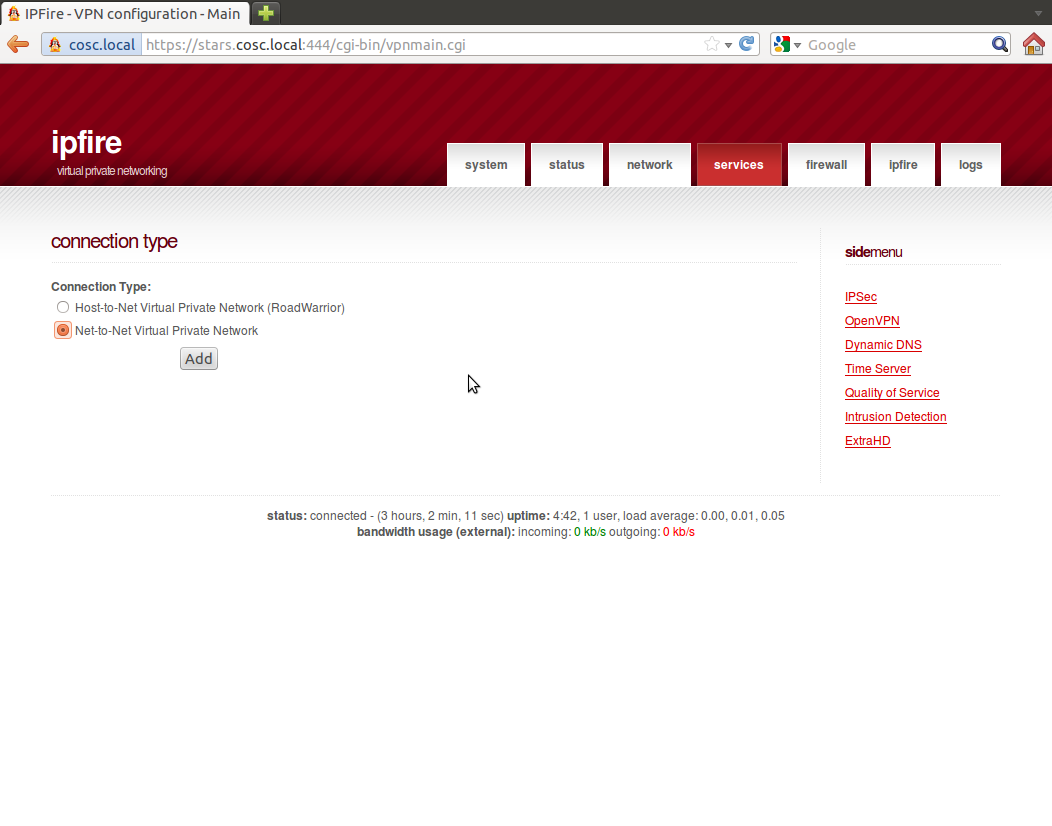
From the section "connection status and control" select Add, then choose Net-to-Net Virtual Private Network
Select a name for the network; in this example I am calling it Green12 to emphasize that I am connecting the GREEN network behind the first host (10.0.3.98) to the GREEN network behind my second system (10.0.3.98). Select the local subnets behind each network; fortunately we already ensured that these were different. You can select your own Local ID’s, but they should start with an "@".
There are a number of ways to provide authentication, but the simplest perhaps is to set up a pre-shared key- effectively just a password.

With these steps completed on the first host, you then repeat the process on the second host. Here I name the connection GREEN21 to emphasize that now we are going from the second (10.0.3.98) back to the first (10.0.3.99). The network settings are modified in the expected fashion as well.

When both sides have been configured, return to "connection status and control"; under status you should see the connection listed as "disconnected" in red. Hit save, and wait a few moments. It should change to green.

You also want to repeat the same process for the ORANGE networks. Doing so (with the same pre-shared key) is simple; you end with something like

Systems behind one GREEN network can directly contact the other; the same holds true for communication between ORANGE networks.
There is one hiccup. A system say on the GREEN 2 network (192.168.2.0/24) can contact
- Public network (10.0.0.0/8 in class) via the firewall
- GREEN 2 (192.168.2.0/24) directly
- GREEN 1 (192.168.1.0/24) via the IPSec tunnel
- ORANGE 2 (172.16.2.0/24) via the firewall
It cannot contact, however systems on ORANGE 1 (172.16.1.0/24) as there is no tunnel and no direct connection.
The upshot of this is that systems on the local network cannot use the local DNS, unless they are behind the same firewall.
The situation for the DMZ systems is fine though, as a system on ORANGE 2 (172.16.2.0/24) can contact
- Public network (10.0.0.0/8 in class) via the firewall
- GREEN 2 (192.168.2.0/24) via the firewall
- ORANGE 1 (172.16.1.0/24) via the IPSec tunnel
- ORANGE 2 (172.16.2.0/24) directly
Thus it can always make its way to the DNS server.
Keep this in mind when setting up your networks!
Take the time to validate your settings. Be sure you can communicate between networks as you expect.
This has been a problematic point among Case Study students for some time, so be sure to allow enough time to debug any problems that arise, well before the final live fire exercise.
 Darknet
- Best EDR Of The Market (BEOTM) – Endpoint Detection and Response Testing Tool
- AgentSmith HIDS – Host Based Intrusion Detection
- padre – Padding Oracle Attack Exploiter Tool
- Privacy Implications of Web 3.0 and Darknets
- DataSurgeon – Extract Sensitive Information (PII) From Logs
- Pwnagotchi – Maximize Crackable WPA Key Material For Bettercap
- HardCIDR – Network CIDR and Range Discovery Tool
- Socialscan – Command-Line Tool To Check For Email And Social Media Username Usage
- CFRipper – CloudFormation Security Scanning & Audit Tool
- CredNinja – Test Credential Validity of Dumped Credentials or Hashes
Windows Security
- An error has occurred; the feed is probably down. Try again later.
Security Focus Vulnerabilities
- An error has occurred; the feed is probably down. Try again later.
Security Bloggers Network
- An error has occurred; the feed is probably down. Try again later.
Krebs on Security
- Patch Tuesday, May 2024 Edition
- How Did Authorities Identify the Alleged Lockbit Boss?
- U.S. Charges Russian Man as Boss of LockBit Ransomware Group
- Why Your VPN May Not Be As Secure As It Claims
- Man Who Mass-Extorted Psychotherapy Patients Gets Six Years
- FCC Fines Major U.S. Wireless Carriers for Selling Customer Location Data
- Russian FSB Counterintelligence Chief Gets 9 Years in Cybercrime Bribery Scheme
- Who Stole 3.6M Tax Records from South Carolina?
- Crickets from Chirp Systems in Smart Lock Key Leak
- Why CISA is Warning CISOs About a Breach at Sisense
